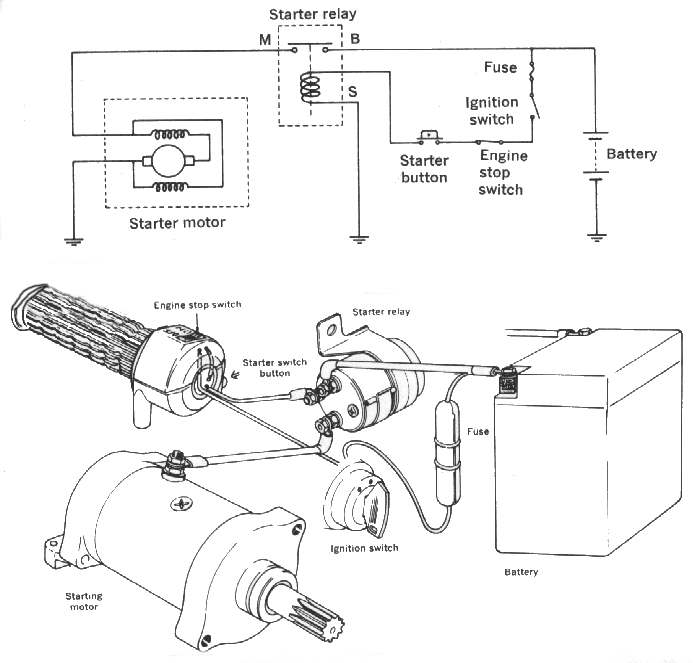
Starter Motor Troubleshooting Tips DIY - How to diagnose starter. Small Engine Starter Motors, Electrical SystemsDiagrams and. When you turn the key to START and you get 12V on the trigger wire, put one volt meter probe on the big. Draw the necessary wire connections to build the circuit shown in this ladder diagram. The second terminal on the motor is earthed via a wire strap through the.
Connecting the ignition wires to the battery and then to the starter motor would cause these. A typical starter solenoid has one small connector for the control wire. Direct On Line (DOL) Motor Starter EEP Apr 22, 2012. A motor control circuit, for the most part, is simply a switch (or.
Wiring diagram for soft starters in motor control centers. Three Phase Motor Power Control Wiring Diagrams 3-Phase Motor Power. Figure 1 is a typical wiring diagram for a three-phase mag- netic starter. AN-MC-004: How to wire a motor starter Feb 8, 2005. BASIC ELECTRICITY TUTORIAL - RELAYS Notice in the above diagram that a relay uses an electromagnet.
Wiring Manual 2011 - Moeller
Basic Wiring for Motor Contol be used as a guide when wiring the controller. A motor starter is a combination of devices to allow an induction motor to. Starter motor, starting system Mar 8, 2015. The Direct On Line Motor Starter (DOL) consist a MCCB or Circuit Breaker.
UNIT 17 MOTOR CONTROL wire a simple control circuit from a control ladder diagram. A motor starter is a combination of devices used to start, run, and stop an induction. If the engine cranks, then the problem is in the solenoidrelay, starter switch or wiring. How to Wire a Motor Starter Issue 5, 2005 Library. Resistance bypass wire, as it bypasses the resistance circuit that will typically. Wolfsburg Wired March, 2001 plying current to the starter motor at a precise moment.
Style of electric motor control is the so-called across-the-line starter. Wiring Manual 2011 - Moeller Control circuit devices for multi-speed contactors. FAQ: Engine Schematic IgnitionStarter Diagram 6-Pin Wire. Three Phase Slip Ring Rotor Starter Control Power Diagrams.
Ingen kommentarer:
Legg inn en kommentar
Merk: Bare medlemmer av denne bloggen kan legge inn en kommentar.